
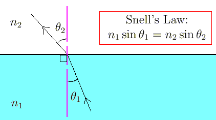
Seismic refraction is a geophysical principle governed by Snell's Law. Used in the fields of engineering geology, geotechnical engineering and exploration geophysics. Seismic refraction traverses (seismic lines) are performed using a seismograph(s) and/or geophone(s), in an array and an energy source. The seismic refraction method utilizes the refraction of seismic waves on geologic layers and rock/soil units in order to characterize the subsurface geologic conditions and geologic structure.
The methods depend on the fact that seismic waves have differing velocities in different types of soil (or rock): in addition, the waves are refracted when they cross the boundary between different types (or conditions) of soil or rock. The methods enable the general soil types and the approximate depth to strata boundaries, or to bedrock, to be determined.
The refraction microtremor method combines the urban utility and ease of microtremor array techniques with the operational simplicity of the SASW technique and the shallow accuracy of the MASW technique. By recording urban microtremors on a linear array of a large number of lightweight seismometers, the method achieves fast and easy field data collection without any need for the time-consuming heavy source required for SASW and MASW work.
By retaining all the original seismograms and by applying a time-domain velocity analysis technique as is done in MASW, the analysis described here can separate Rayleigh waves from body waves, airwaves, and other coherent noise. Transforming the time-domain velocity results into the frequency domain allows the combination of many arrivals over a long time period, and yields easy recognition of dispersive surface waves.
Seismic Refraction and Geophone
Energy is introduced by using one of a number of possible seismic sources. Common sources include seismic shotgun, small dynamite charges, weight drop or rammer sources. In some environments, such as gassy deltaic sediments, a shear wave source and geophones are used. The returning wavefield is recorded in the seismograph from a spread of geophone receiver groups. The number of geophones used may be as few as 24 in favorable environments to many times more where high subsurface sampling redundancy is required.
The goal of a high-resolution seismic survey is to provide an image of the subsurface that is as detailed as possible, within the limits imposed by the nature of acoustic wave propagation in the earth. The 2D seismic method entails propagation of the acoustic waves through the earth from a surface pattern of source and receiver points.
The survey procedure entails the collection of a seismogram, then advancing the energy source a fixed distance down the survey line and repeating the process to receive another seismogram. This method known as common mid-point (CMP) provides a very high degree of redundancy of sampling of the energy received from a given reflector at depth. The redundancy is used in the data processing procedure to develop a high-fidelity image of the subsurface. If all receiver locations are used as shot points, the multiplicity of data on one subsurface point (called CMP or CDP fold) is equal to one half of the number of recording channels.
A number of seismic events are present in each seismogram in addition to the reflections of interest. Data processing steps designed to attenuate this unwanted energy, and enhance the reflections of interest are carried out. The ultimate product of the reflection processing is a corrected cross section with reflection events ready for interpretation.
The SEGY formatted seismic data is imported into the Seismic Micro Technologies (SMT) 2D/3D seismic interpretation package, together with survey line position information. This software is a comprehensive 2D/3D seismic interpretation program that provides interpretive and horizon picking tools, integrated into a map and section database, entity management, and display system.
The initial step in the seismic data interpretation process is the correlation of the major geological structures to seismic reflectors. The process of tracing reflectors within a given seismic line, and from line to line at tie points, requires careful phase correlation of the events.
During this process sedimentational character, and stratigraphic features and faulting are considered. A velocity model is developed during processing, and by correlation with borehole geologic and velocity logging information. The times associated with each of the interpreted reflectors are then converted from time sections into depth sections using this model.